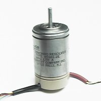
| A resolver is a form
of synchro
in which the windings on the stator are displaced
mechanically by 90 degrees
to each other, while the Synchro is displaced by
120 degrees. Resolvers
are used most often as an angle measurement
transducer whose "analog" output
is converted to a "digital" format using a Synchro-to-Digital
Converter (S/D or R/D). |
 |
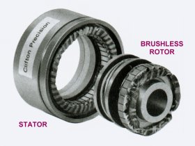
Many Resolvers today
are "brushless" types (as
shown at right) where, instead of using "brushes"
and slip rings, the rotor
excitation is "transformer" coupled to the shaft
rotor winding. Resolvers
of this type are very reliable, and can be used in
the most demanding applications.
Resolvers come in a variety of shapes and sizes,
many of which are designed
(electrically & mechanically) for specific
applications.
|
 |
| The electrical
schematic for a resolver is shown
to the right. Resolvers (like 3- wire
Synchros) can be thought of
as "variable transformers". Shaft angle
rotation, with an "AC" voltage
applied to the "Rotor" shaft winding, causes a
change in the Resolver's
"stator" output voltage. |
 |
|